 Question Constellation Sign up for free
 AQA · GCSE · Combined Science · Higher
Changing an LED circuit
The camera in a mobile phone uses an LED to provide light when taking a photograph. A student investigated how the potential difference across an LED varies with current in it. Figure 9 shows the circuit used.
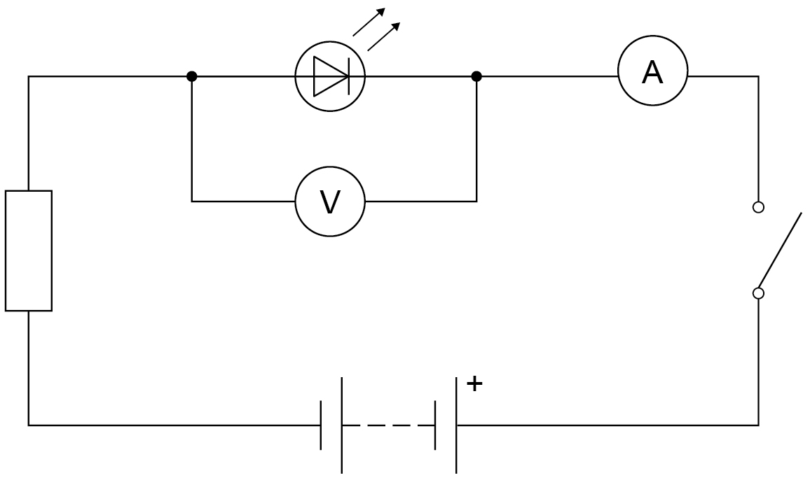
The student closed the switch. The voltmeter gave a reading of 5.0 V
The ammeter gave a reading of 0 mA
The LED did not emit any light.
Explain how the student should have changed the circuit to make the LED emit light.
Write your answer first. You can study the marking guidance whenever you need it.
Study the marking See what earns credit and compare it with a full-mark answer.
Marking points
- 1 Say that the student should reverse the connections to the LED or to the battery.
- 2 Explain that an LED or diode only allows current through in one direction.
Full-mark answer
The student should reverse the connections to the LED or the battery, because an LED only allows current through in one direction.
Why this answer loses marks
The student should increase the voltage so the LED lights.
The voltmeter already reads 5.0 V across the LED but the current is 0 mA, so the issue is the LED direction, not simply the size of the potential difference.